


Adding TCP/IP connections to an OS/400 system is not difficult, but it does require planning and a clear understanding of TCP/IP and your network. There are several reasons for adding additional TCP/IP interfaces to your iSeries and AS/400 server. Sometimes extra hardware is required, while at other times it requires you to define an additional interface using the existing hardware. In this article and its companion pieces, I will focus on how you can add TCP/IP LAN interfaces to your OS/400 system and cover some key topics:
• The basic terminology and the difference between a TCP/IP interface and an OS/400 communication adapter. (See the sidebar article, “Basic Concepts for OS/400 TCP/IP Configuration.”)
• Why you would need to add additional interfaces to your system
• The basic information needed to add an interface
• The steps you need to follow in adding an interface
• Some of the routing considerations that arise when multiple interfaces are added to an OS/400 system. (See the second sidebar article “Configuring OS/400 TCP/IP Interfaces for Multiple Subnets.”)
By the time you finish this material, you should learn enough about OS/400 TCP/IP interfaces to become an expert in the field.
Network Topology
A TCP/IP network is comprised of one or more segments or subnets that are typically joined together by routers. Figure 1 shows an example of a TCP/IP network that can be built using switches rather than routers. In this case, the switch handles isolating the traffic and makes the network look like one large subnet to TCP/IP.
TCP/IP routing is done on a hop-by-hop basis between networks, based on the destination IP address in the packet header. Once the packet reaches the destination network, it is delivered to the designated host by using the link layer protocol (such as Ethernet) of the subnet. For outgoing messages, a TCP/IP route table is used to select a path out of the system. Each segment of the network has a network address. TCP/IP uses
the route destination and the subnet mask that is specified on the route entry to determine which network addresses should be reachable by which paths.
There are several ways to add entries to the OS/400 route table. When an interface is added to a system, a route entry is automatically added. Route information may be received from other systems in the network, and routes may be added manually by a network administrator. The green-screen Work with TCP/IP Network Status (NETSTAT) command can be executed as follows to display all the routes in the OS/400 route table.
NETSTAT OPTION(*RTE)
Your physical network layout determines what, if any, route entries are needed. A LAN with all the hosts on a single segment (as outlined in Figure 1) may not need any route entries. A LAN comprised of multiple segments (such as I describe in our companion piece, “Configuring OS/400 TCP/IP Interfaces for Multiple Subnets”) connected by routers or gateways (another name for routers) will need at least one route entry. A system that is connected to a private intranet and the Internet will probably need at least two route entries for directing traffic.
TCP/IP Load Balancing
Load balancing means different things to different people, and it can be discussed in reference to the direction of the traffic being handled. For example, there can be both inbound and outbound load balancing. Load balancing can also be discussed in terms of balancing the load based on the actual load on the physical adapters or based on the number of connections across the interfaces. OS/400 servers have built-in support for outbound connection (load) balancing. If you are adding additional physical adapters to provide more bandwidth, then you will want to take advantage of outbound load balancing. Outbound load balancing is enabled by using duplicate route entries for the same route destination. Inbound load balancing is implemented using a virtual IP address on the system and an external device to distribute the traffic across the adapters. Most routers provide a round- robin function to provide this support.
Implementation
There are two OS/400 user interfaces available for working with your TCP/IP configurations: the AS/400 Operations Navigator (OpsNav) GUI and the OS/400 command line. In most cases, I will display both methods for configuring our sample interfaces. You may also access the TCP/IP configuration commands using the green-screen Configure TCP/IP (CFGTCP) command, which displays a menu for configuring OS/400 TCP/IP features. The user profile you use to administer TCP/IP must have I/O system configuration authority (*IOSYSCFG) in order to perform most of these tasks.
Collecting the Required Information for an Interface
To add an OS/400 system interface, you will need to collect some basic information. You need to know the OS/400 hardware resource name, hardware location, or the line description name if a line already exists for the hardware resource. You will also need the IP address and subnet mask that is going to be assigned to the new interface. If the interface is going to access the host by a name, then you will need to know the host and domain name assigned to this address. A single host name may point to multiple addresses. I recommend using a Domain Name System (DNS) server to resolve the host name to IP address translation. This eliminates most of the need for host table entries on the local system.
Verify the Hardware and Line
Locate the OS/400 hardware adapter you are going to use and make sure it is plugged into the network correctly. To see a list of your communications hardware using OpsNav, double click on your system’s Configuration and Service > Hardware Inventory > Communications path in OpsNav. Double click on any resource name (CMNxx, where xx is equal to a number). The Properties panel is displayed. Click the Physical Location tab. The location information is displayed. However, be aware that this panel will not show the lines built on the resource.
On the green-screen, run the Work with Hardware Resources (WRKHDWRSC) command with hardware type (*CMN) as follows to list all the communication adapters found on the system:
WRKHDWRSC TYPE(*CMN)
On the WRKHDWRSC screen, the text description field tells you the type of adapter (e.g., Communications Adaptor,Ethernet port) you are using. Use Display resource detail (option 7) to display the adaptor’s location information. Use Work with configuration descriptions (option 5) to determine if the adapter has any lines currently defined. If there is a line defined and you plan to use it for TCP/IP traffic, you need to determine if the line is configured to support TCP/IP. To support TCP/IP, the line must have a Source Service Access Point (SSAP) of AA defined. If the SSAP is not configured on the line, it may be added by using the Change Line Description (CHGLINxxx, where xxx is the type of line) command, such as the Change Line Description (Ethernet) (CHGLINETH) command, and adding a new AA SSAP under the SSAP parameter. CHGLINxxx can also be accessed by bringing up the Work with Line Descriptions (WRKLIND) command and selecting Change (option 2) on the line that you want to configure. Your target line must be varied off to perform this operation. Be careful here, varying off the line will end all sessions using that line. If the line resource is part of a File Server input/output adapter (IOA), you may need to create a network server description to build the line description. (OpsNav sets up the AA SSAP for you when you use it to create your line, but there is no way to configure an already existing line in OpsNav to add the AA SSAP. For that task, you must go to the green-screen.) Refer to the Redbook iSeries System Handbook Version 4 Release 5 (GA19-5486-20) for additional hardware configuration information.
Determine the IP Address and Subnet Mask
The network topology and the location of the interface in the network will help you determine the IP address and subnet mask for the interface you are adding. You will be given the address and subnet mask by a network administrator or, in some cases, by an ISP. If you have to generate the address and subnet mask yourself, you should pick an address that is valid for the segment and, most of all, the IP address must be unique. The subnet mask should be the same as that used on the other hosts in the segment.
Adding an Interface to an Existing Line Description
In this example, you will add a new TCP/IP interface to an existing line. You will use this interface for a new occurrence of an HTTP server for AS/400 server instance. The information needed for this example is the IP address, subnet mask, line name, and host name.
Refer to the Collecting the Required Information for an Interface section in this article for details about gathering the information needed to build this interface. In this example, I will assume that you collected very specific information:
• The existing line name is ETHLINE1
• The IP address is 10.1.1.111
• A Subnet mask of 255.255.255.0 will be used
• The name is WWW1.MYDOMAIN.COM
To add the interface using the OpsNav GUI, open the Network > Protocols path. Right click on the TCP/IP icon in the left window and select New Interface, Local Area Network from the pop-up menu that appears. The New TCP/IP Interface wizard welcome screen will appear. Click Next. Select the LAN connection type you’ll be using on the TCP/IP Interface Type screen that appears, and click Next.
A panel similar to the new TCP/IP Interface Resource screen shown in Figure 2 will appear. Select the List by lines radio button. A list of the existing lines that match the LAN type you selected will appear. In our case, you would select the ETHLINE1 line and click Next. Figure 3 displays the TCP/IP Interface Settings screen that appears. The Interface name and network name fields must be entered. You should put meaningful values in these fields. Type the IP address and subnet mask into the correct fields. The network address and host address are calculated and displayed when you tab out of the subnet mask field. Verify that these values are correct. Click Next and the routing panel is displayed. In this example, you are simply adding another address to an existing line so no additional routing is required. Click Next and make the proper selections for your environment on the following screens until you receive the New TCP/IP Summary panel, as shown in Figure 4. Verify the information and click Finish. The new interface is now defined on your system, and it will start if you had selected the option to automatically start during your configuration.
To add the same interface using the command interface, you can type the following Add TCP/IP Interface (ADDTCPIFC) command as one line and press enter:
ADDTCPIFC INTNETADR(‘10.1.1.111’) LIND(ETHLINE1) SUBNETMASK(‘255.255.255.0’)
To start the interface using the command interface, type in the Start TCP/IP Interface (STRTCPIFC) command as shown and press enter:
STRTCPIFC INTNETADR(ipaddress)
where ipaddress is the TCP/IP address of the interface to start.
Checking and Changing the Status Of Interfaces
To verify or change the status of the interface in OpsNav, you can right click the TCP/IP icon in the left window of the OpsNav Network > Protocols path. Click Interfaces from the pop-up menu and the TCP/IP Interfaces panel will appear and display the status of the interface. The NETSTAT command also provides menus for checking and changing the status of interfaces, routes, and connections. Use the F4 command to prompt NETSTAT to show you the different types of network status displays you can access.
Adding a Host Name
If you are using a DNS server, follow the steps you would normally use to add a new host name. If you need to add the host name to the OS/400 host name table on the server, open the TCP/IP properties window in OpsNav by double clicking TCP/IP in the left window and selecting the Host Table tab. Click the Add button in this window and follow the prompts to add a new host name to your iSeries and AS/400.
To add the host name using the command interface, type the Add TCP/IP Host Table Entry (ADDTCPHTE) command and press enter:
ADDTCPHTE INTNETADR(ipaddress) HOSTNAME((host))
ipaddress is the TCP/IP address of the new interface and host is the name you want to assign to this system.
Adding an Interface and a New Line Description
Now, I will discuss a different example that is based on Figure 1, where you already have a line and an interface for the 10.1.1.11 interface. Now you will want to add a second line and assign it to the 10.1.1.12 interface. In this situation, you are adding TCP/IP capacity. You are also enabling outbound load balancing between the two interfaces and lines using route statements. All the inbound traffic will arrive through our existing interface, so additional DNS or host names are not required, but the outbound traffic will go through both the existing line and the new line. To add the new line to your configuration, the information needed for this example is the IP address, subnet mask, and hardware resource. The line description object name’s only requirement is that it must be unique on the system. You must also change the route entries for the existing interface 10.1.1.11. This example is based on Figure 1, so you should have collected specific information for the new second line:
• The new IP address is 10.1.1.12
• The Subnet mask is 255.255.0.0
• The resource name to use is of CMN04
• The subnet supports Full duplex and 100 Mbps Ethernet
To add the interface using the OpsNav GUI, open the Network > Protocols path. Right click on the TCP/IP icon in the left window and click on New Interface > Local Area Network from the pop-up menu. Go through the configuration as outlined above, but this time choose the List by hardware resource names radio button on the New TCP/Interface IP Resource screen, which brings up a list of all the eligible hardware resources for which you could create a new TCP/IP line and interface (Figure 2). Select the resource name CMN04. The next screen that appears is the Creating a New Line Description screen, similar to Figure 5, where you input all the attributes of the line you are creating, including the line name and the duplex field. The drop-down duplex field box will contain all the available options, based on your hardware. Refer to the help text and select the best values for your network. Full Duplex is typical for speed in processing requests. Click Next. The wizard will then prompt you for line speed and protocol values on the Ethernet Line Characteristics screen. Select the line speed and required protocols based on your network hardware (100 Mbps is typical). Click Next. The TCP/IP Interface Settings screen (which is the same screen I showed you in Figure 3) contains the Interface name, network name, IP address, and subnet mask on the TCP/IP Interface Settings screen. As before, the network address and host address are calculated and displayed when you tab out of the subnet mask field. Verify that these values are correct and click Next.
At this point, a TCP/IP Routing screen will be displayed. The default behavior of TCP/IP with multiple interfaces into the same LAN segment is to choose one interface and to use only that interface for routing TCP/IP traffic. You want to enable outbound load balancing
Routing
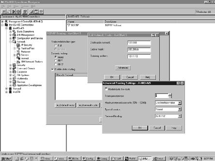
so that both interfaces (10.1.1.11 and 10.1.1.12) can be used to route outbound traffic. This requires changes to the existing routes for 10.1.1.11 (see Changing the Existing Routes section in this article) as well as a new route for 10.1.1.12. To enable this support, you must specify the Route Precedence and Preferred Binding address entries on your routing entries. These values are not added to the system-generated route entries, so you need to specify additional routing information. To do that, select Yes at the prompt, Would you like to set additional routing information for this network interface radio box, and click Next. A second TCP/IP Routing Screen will appear. Click on the Enable static routing check box to enable static routing, then click on the Add network route button. Type the network address of the local network (10.1.0.0) in the Destination network field, the subnet mask in the Subnet mask field (255.255.0.0), the new interface address (10.1.1.12) in the Preferred Binding Interface field, and the interface address (10.1.1.12) in the Gateway address field, and click the Advanced button. On the Advanced screen, change the Route Precedence to 6 and click OK. Click OK again and the route entry is added. (Note: in some versions of OpsNav, the Preferred Binding field is listed on the Advanced screen.) This entire sequence of events for adding the new network route for this interface are shown in Figure 6.
Completing the Interface Configuration
After you’ve added to the routing values, click Next and make the proper selections for your environment. Continue the process until you receive the New TCP/IP Summary panel, which is the same panel you saw in the previous example (as shown in Figure 4). Verify the information and click Finish. The interface is now defined and will be started automatically, if you selected the autostart option during configuration. Refer to the section Checking and Changing the Status of Interfaces in this article to verify or change the status of the interface.
Using the Command Interface to Build the Configuration
The same configuration can be built using the command line interface. To add the same line, interface, and route using the command interface, type in the following three green- screen commands and press enter after each command:
• To create the line description, use the CRTLINETH command:
CRTLINETH LIND(ETHLINE2) RSRCNAME(CMN05) TCPONLY(*YES) LINESPEED(100M) DUPLEX(*FULL)
• To add the TCP/IP interface, enter the ADDTCPIFC command with these values:
ADDTCPIFC INTNETADR(‘10.1.1.12’) LIND(ETHLINE2)
SUBNETMASK(‘255.255.0.0’)
• To add a new routing entry for the 10.1.1.12 TCP/IP interface, run the Add TCP/IP Route (ADDTCPRTE) command, as follows:
ADDTCPRTE RTEDEST(‘10.1.0.0’) SUBNETMASK(‘255.255.0.0’) NEXTHOP(‘10.1.1.12’)
BINDIFC(‘10.1.1.12’) DUPRTEPTY(6)
Refer to the section Checking and Changing the Status of Interfaces in this article to verify or change the status of the interface.
Changing the Existing Routes
To complete the task of enabling outbound load balancing, you must make a change to the existing route entry for the 10.1.1.11 interface if a routing entry exists, or add a new route
entry for 10.1.1.11 if one does not exist. The interface must be inactive to make the change. This means that all the traffic coming into that address will be stopped. Therefore, you must plan a brief network outage so you can update the interface.
Creating a Network Outage
Your new interface (10.1.1.12) must be started. Point your OpsNav session to the new address (10.1.1.12) and start a connection. Right click the TCP/IP icon in the left window. Click Interfaces from the pop-up menu, and the TCP/IP Interfaces panel will appear. Select your original interface (10.1.1.11) and click Stop. Refresh the panel until the status changes to inactive. When the status goes inactive, click the Open button. On the next panel, click on the General tab, and then click on the Routes button. If your network matches that shown in Figure 1, then you should not have any route entries for this interface. Record the information about any route entries that you find. Determine why they are there and then, if these routes aren’t needed, remove them. You must enable static routing the same way you enabled static routing for the 10.1.1.12 interface (Figure 6). On the TCP/IP Routing screen, click on the Enable static routing box, then click on the Add network route button. Type the network address of the local network (10.1.0.0) in the Destination network field, the subnet mask in the Subnet mask field (255.255.0.0), and the interface address (10.1.1.11) in the Gateway address field, and click Advanced. Change the Route Precedence to 6 and make sure the Preferred binding field is equal to 10.1.1.11. Click OK to save and click OK again to add the route entry. Restart the 10.1.1.11 interface. You should be able to communicate using the original IP address.
If you’re changing the 10.1.1.11 routing configuration by using the green-screen, end the 10.1.1.11 TCP/IP interface by typing in the End TCP/IP Interface (ENDTCPIFC) command:
ENDTCPIFC INTNETADR(‘10.1.1.11’)
Add a new routing entry to the interface by typing in the ADDTCPRTE command, like this:
ADDTCPRTE RTEDEST(‘10.1.0.0’) SUBNETMASK(‘255.255.0.0’) NEXTHOP(‘10.1.1.11’)
BINDIFC(‘10.1.1.11’) DUPRTEPTY(6)
Then restart the interface using the STRTCPIFC command:
ENDTCPIFC INTNETADR(‘10.1.1.11’)
You should be able to communicate again by using the original IP address.
Wrapping It Up
These examples should serve as a guide as you plan to add new interfaces. Remember that you must have a clear understanding of your network before you begin making changes. A network diagram is a simple but valuable tool when making changes. Above all else, remember to write everything down and make sure that you make a solid plan before you begin.
References and Related Material
Address Allocation for Private Internets, (RFC1918), Internet Engineering Task Force Web site:www.ietf.org/rfc/ rfc1918. txt?number=1918
iSeries System Handbook Version 4 Release 5, Redbook (GA19-5486-20), IBM Redbook Web site: www.redbooks. ibm.com
TCP/IP Tutorial and Technical Overview, Redbook (GG24-3376-05), IBM Redbook Web site: www.redbooks. ibm.com
V4 TCP/IP for AS/400: More Cool Things Than Ever, Redbook (SG24-5190), IBM
Redbook Web site: www.redbooks.ibm.com Figure 1: Here’s a simple TCP/IP network where the internal use of switches makes the network look like one large TCP/IP subnet.
Figure 2: The OpsNav GUI provides one method of adding TCP/IP interfaces.
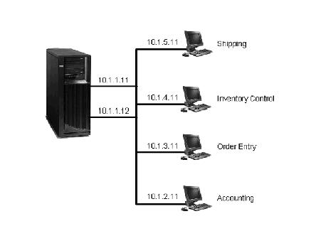
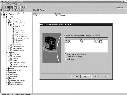
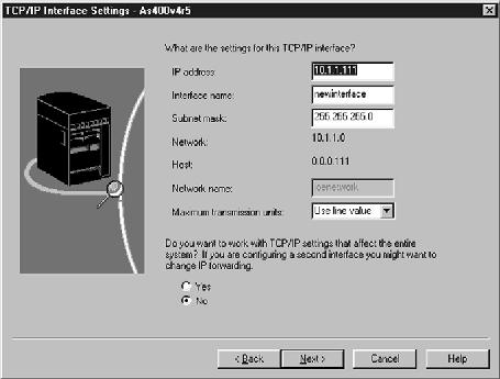
Figure 3: OpsNav provides an easy setting for describing your TCP/IP interface settings.
Figure 4: After you add a new OS/400 TCP/IP, this is what the summary screen looks like.
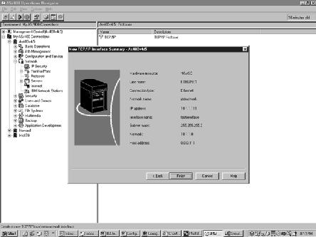
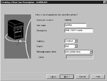
Figure 5: You can also use OpsNav to create a new line description on the fly as you are creating your new TCP/IP interface.
Figure 6: Here’s the entire sequence of events for adding a new network route for a OS/400 TCP/IP interface.
Basic Concepts for OS/400 TCP/IP Configuration
The two major components used to define TCP/IP connections on an OS/400 server are TCP/IP interfaces (software) and communication adapters (hardware). From a software perspective, an interface is the logical definition that describes a TCP/IP connection that is used to communicate with the rest of the world. An interface is also used to assign one or more TCP/IP addresses to a communications adapter. The number of addresses that can be assigned to a single adapter varies based on your version of hardware and software.
In contrast, a communications adapter is the actual physical hardware, such as an Ethernet or a WAN adapter, and it is defined on an OS/400 server by a line description (*LIND) object. TCP/IP interfaces can be defined to work over different types of communication adapters, and one physical adapter will support many different TCP/IP interfaces. Interfaces that are not associated with a line description can also be built inside OS/400. These interfaces, known as circuitless or virtual IP interfaces, can be used to define TCP/IP addresses that are not dependent on physical adapters.
From a hardware perspective, to connect your OS/400 system directly to a new LAN segment, you need to add an additional adapter. Another reason for adding an additional adapter is to increase the amount of traffic that can flow between the system and the LAN. If you have a situation where you only need an additional TCP/IP address on your system, such as running multiple HTTP servers on the same iSeries server, an additional adapter may not necessarily be needed.
TCP/IP Addressing
An IP address is the means by which one system (host) directs traffic to another host on the network. The current version of OS/400 TCP/IP uses a 32-bit address. This IP address is written in dotted decimal notation by dividing the address into four groups of eight bits each and converting each group (octet) into a decimal number. Each octet is separated by a decimal point (e.g., the IP address 00001010 00000001 00000001 00000001 is written as 10.1.1.1). Each interface in the network must have a unique address.
There are two types of IP addresses: public addresses that route through the Internet and private IP addresses that work only in a private intranet. Public addresses are obtained from an Internet registry, such as an ISP, and should only be assigned to system interfaces that need direct Internet access. Private addresses should be used for the interfaces on systems that need to communicate using TCP/IP within an enterprise. If these systems need access to the Internet, they will route though a system, router, or firewall with access to the Internet. Three ranges of addresses have been reserved by the Internet Assigned Numbers Authority (IANA) for use as private addresses:
10.0.0.0 to 10.255.255.255
172.16.0.0 to 172.31.255.255
192.168.0.0 to 192.168.255.255
For more details about the use of these address ranges, refer to Address Allocation for Private Internets (RFC1918), which can be found on the Internet Engineering Task Force Web site located at www.ietf.org. Avoid the 192.168 address range for your interfaces because OS/400 network server descriptions (*NWSD) and some LPAR connections use this address range to build the internal LAN connection to the iSeries.
Network Mask
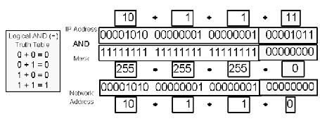
An IP address consists of two parts: the network address and the host address. The network mask or subnet mask is a 32-bit-wide mask that is used to specify which bits are allocated for each portion, and it is written in dotted decimal notation. The network mask is used in a logical AND operation by the system to derive the network address of the segment into which the interface is plugged. Any bit that is set to one in the mask is considered as part of the network address. Any bit that is set to zero in the mask is considered the host portion of the address. Figure A shows how a mask is used to determine the value of the network address. The way the mask is set up determines the number of network segments you can have and the number of host interfaces that can be defined on one segment. All the interfaces connected to a network segment will have the same network address.
Now, Back To the Configuration
Once you know these main concepts for TCP/IP configuration, it will be easier to configure new TCP/IP interfaces on your iSeries and AS/400. Now that you’ve got some basics, you’re in a position to better handle your OS/400 TCP/IP setup.
—Fant Steele III
Figure A: This is how a subnet mask is used to determine the value of a network address.
Configuring OS/400 TCP/IP Interfaces for Multiple Subnets
As opposed to the relatively simple TCP/IP configuration I created in the “Configuring TCP/IP Connections on an iSeries andAS/400” article, Figure A outlines an example of a more complex network built with multiple routers connecting five subnets. A network can and should be segmented into subnets for many reasons, including performance issues and network load considerations, different types of network hardware, and the physical location of the network segments. Subnet A, as shown in Figure A, is a 100 Mbps Ethernet backbone located in a main office building. Subnet B is a 100 Mbps segment used by accounting, which is also housed in the main office building. Order Entry (Segment C), Inventory Control (Segment D), and Shipping (Segment E) are located in the warehouse building and are connected with the main office building via fiber optic cable. Segments D and E require an additional router because they are wireless LANs used for communication throughout the warehouse.
Implementing a More Complex Network
To implement this environment in your OS/400 network, first add the interfaces and line descriptions for the two-line setup (10.1.1.11 and 10.1.1.12) by following the procedures that were outlined in the main article. You also need to add the routing entries that are described in the main article with one exception: The subnet mask on the interface will now change to 255.255.255.0 to allow for the addition of routers in the environment (remember, in the example that I used in the main article, there were no subnets). To route information to the Internet and each of the five subnets that are shown in Figure A, you will also use a more advanced technique with the subnet mask on the route entries that allows you to use four route entries per interface. Here’s how to set up your TCP/IP for this environment using either AS/400 Operations Navigator (OpsNav) or green-screen commands.
More Complex Routing Using OpsNav
To implement a more complex network, you will want to enable outbound load balancing for the line description and the 10.1.1.12 interface. This requires changes to the existing routes (see the Changing the Existing Routes section in the main article) for both the 10.1.1.11 and 10.1.1.12 interfaces. Start with the
10.1.1.12 interface that you added fresh, as directed in the main article. Once you’ve completed the basic steps for configuring the ETHLINE2 line description and the 10.1.1.12 interface, select Yes when you get to the routing step where the wizard asks if you want to specify additional routing information. Then click Next. In Figure B, click on Yes in the AS/400 Operations Navigator screen to display the TCP/IP routing screen. You must enable static routing by checking the Enable Static Routing check box on the screen. (Note: The TCP/IP Routing screen for an interface can also be reached in OpsNav by stopping the interface in OpsNav, opening the Interface properties, and clicking on the Routes button under the General tab of the interface properties screen, which means that this configuration can also be done after you configured the line and interface in OpsNav.)
Once static routing is enabled, you can add the four routing entries for each of the four subnets shown in Figure A (one routing entry for Subnets A, B, and default Internet traffic; and one routing entry to direct traffic to Subnet C, which will handle the routing for Subnets D and E) by following these steps:
1. Start by clicking the Add network route button on the TCP/IP Routing screen.
2. Type the network address of subnet A (10.1.1.0) in the Destination network field, the subnet mask
(255.255.255.0), in the Subnet mask field, and the interface address (10.1.1.12) in the Gateway address field, then click Advanced. Change the Route Precedence to 6 and click OK.
3. Click OK again and the route entry is added.
4. Click Add network route again.
5. Type the network address of subnet B (10.1.2.0) in the Destination network field, the subnet mask
(255.255.255.0) in the Subnet mask field, and the interface address of router X (10.1.1.2) in the Gateway address field, then click Advanced.
6. Change the Route Precedence to 6 and click OK.
7. Click OK again and the route entry is added.
Now, you will add the route for networks C, D, and E using a larger subnet mask by following these steps:
1. Click Add network route.
2. Type the network address of subnet C (10.1.0.0) in the Destination network field, the subnet mask
(255.255.0.0) in the Subnet mask field, and the interface address of router Y (10.1.1.3) in the Gateway address field, then click Advanced.
3. Change the Route Precedence to 6 and click OK. Click OK again and the route entry is added.
Follow these steps to set up the last route entry for the Internet, which will be a default route entry:
1. Click the Add default route button.
2. Type the interface address of the firewall (10.1.1.1) in the Gateway address field and click Advanced.
3. Change the Route Precedence to 6 and click OK.
4. Click OK again and the route entry is added.
You now have four routes specified for the 10.1.1.12 interface. When TCP/IP looks for a path, it tries to match the most specific entry first, moving on to the most generic entry. This means that traffic for 10.1.1.x (subnet A) matches the first route entry; 10.1.2.x (subnet B) matches the second route entry; traffic for the rest of the 10.1.x.x network matches the third route entry; and any other traffic matches the default route entry, which forwards the traffic to the firewall. Now that you have added all the routes, you should continue configuring your new interface as described in the main article (if you added these route entries during interface setup). After you complete the steps, return here to complete the process.
More Complex Routing Using the Command Line
To build this configuration using the command interface, use the following commands:
• Create the line using the Create Line (Ethernet) (CRTLINETH) command:
CRTLINETH LIND(ETHLINE2) RSRCNAME(CMN05) TCPONLY(*YES) LINESPEED(100M) DUPLEX(*FULL)
• Add the interface to the line using the Add TCP/IP Interface (ADDTCPIFC) command:
ADDTCPIFC INTNETADR(‘10.1.1.12’) LIND(ETHLINE2) SUBNETMASK(‘255.255.255.0’)
Add the routing entries for each of the four destination subnets (Subnet A, Subnet B, Subnet C, D, and E, and the default):
• Subnet A:
ADDTCPRTE RTEDEST(‘10.1.1.0’)
SUBNETMASK(‘255.255.255.0’) NEXTHOP(‘10.1.1.12’)
BINDIFC(‘10.1.1.12’) DUPRTEPTY(6)
• Subnet B:
ADDTCPRTE RTEDEST(‘10.1.2.0’)
SUBNETMASK(‘255.255.255.0’) NEXTHOP(‘10.1.1.2’)
BINDIFC(‘10.1.1.12’) DUPRTEPTY(6)
• Subnet C, D, and E:
ADDTCPRTE RTEDEST(‘10.1.0.0’)
SUBNETMASK(‘255.255.0.0’) NEXTHOP(‘10.1.1.3’)
BINDIFC(‘10.1.1.12’) DUPRTEPTY(6)
• Default route for all other traffic:
ADDTCPRTE RTEDEST(*DFTROUTE) SUBNETMASK(‘255.255.0.0’) NEXTHOP(‘10.1.1.1’)
BINDIFC(‘10.1.1.12’) DUPRTEPTY(6)
To complete this configuration, you also need to change the routes for the 10.1.1.11 interface to enable outbound load balancing. This requires the removal of the existing route entries and the addition of a new set similar to the set created for 10.1.1.12. (The only difference between the two sets is the Preferred binding interface value of 10.1.1.11 rather than 10.1.1.12.) This can be done through OpsNav by stopping the interface in OpsNav, opening the Interface properties, and clicking on the Routes button that is under the General tab of the interface properties screen. You can also perform this function by copying and modifying the green-screen commands listed. Refer to the Changing the Existing Routes section of the main article for details and cautions.
—Fant Steele III
Figure A: After you get the simple TCP/IP configurations down, you can move to a more complicated OS/400 TCP/IP setup like this one.
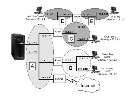
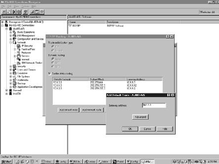
Figure B: To implement more complex TCP/IP setups in OS/400, you add several routing entries in either OpsNav or on the green-screen.

 More than ever, there is a demand for IT to deliver innovation. Your IBM i has been an essential part of your business operations for years. However, your organization may struggle to maintain the current system and implement new projects. The thousands of customers we've worked with and surveyed state that expectations regarding the digital footprint and vision of the company are not aligned with the current IT environment.
 TRY the one package that solves all your document design and printing challenges on all your platforms. Produce bar code labels, electronic forms, ad hoc reports, and RFID tags – without programming! MarkMagic is the only document design and print solution that combines report writing, WYSIWYG label and forms design, and conditional printing in one integrated product. Make sure your data survives when catastrophe hits. Request your trial now! Request Now.
 Forms of ransomware has been around for over 30 years, and with more and more organizations suffering attacks each year, it continues to endure. What has made ransomware such a durable threat and what is the best way to combat it? In order to prevent ransomware, organizations must first understand how it works.
 Disaster protection is vital to every business. Yet, it often consists of patched together procedures that are prone to error. From automatic backups to data encryption to media management, Robot automates the routine (yet often complex) tasks of iSeries backup and recovery, saving you time and money and making the process safer and more reliable. Automate your backups with the Robot Backup and Recovery Solution. Key features include:
 Business users want new applications now. Market and regulatory pressures require faster application updates and delivery into production. Your IBM i developers may be approaching retirement, and you see no sure way to fill their positions with experienced developers. In addition, you may be caught between maintaining your existing applications and the uncertainty of moving to something new.
 IT managers hoping to find new IBM i talent are discovering that the pool of experienced RPG programmers and operators or administrators with intimate knowledge of the operating system and the applications that run on it is small. This begs the question: How will you manage the platform that supports such a big part of your business? This guide offers strategies and software suggestions to help you plan IT staffing and resources and smooth the transition after your AS/400 talent retires. Read on to learn:
LATEST COMMENTS
MC Press Online