


Back in the good old ’80s, there was a movement lead primarily by a bunch of software vendors to get IT managers to buy into something called computer-aided systems engineering (CASE) tools. By providing a means of documenting business processes, these tools were touted to be all you would ever need for software development in the future. Map out the process, and voilá, you had instant bug-free software in a language of your choosing.
The tools shared some unique attributes: All used some sort of modeling language or diagramming tool to represent the business process, all implemented some sort of development methodology, and all were expensive—very expensive. Oh, and did I say that these tools were expensive?
Most, if not all, of those initial publishers are gone now, not having withstood the test of time. But they did serve to highlight an aspect of software development often ignored: the need to document and model the business process as a part of the software creation effort.
Around the ’90s, there was a movement advocating the development of software using object-oriented techniques. Object orientation was an entirely new development paradigm, and a number of the leading advocates put together their own methodologies for mapping processes and translating that mapping into quality software. Names like Grady Booch, Jim Rumbaugh, and Ivar Jacobson were heard leading the charge, with their methodologies known respectively as Booch, Object Modeling Techniques (OMT), Objectory, and others. In 1994, Rumbaugh joined with Booch to begin the unification of their methodologies.
Ivar Jacobson pioneered the concept of use cases in his Objectory method, first published in 1993. Both Booch and Rumbaugh had started to implement them into their method offerings, a fact that made it very natural for Jacobson to join the unification effort in 1995.
The Unified Modeling Language (UML) was the result of this joint endeavor. UML represents the combination of the Booch, Objectory, and OMT methods, and additionally incorporates ideas from a who’s who of other methodologists, including Wirfs-Brock, Ward, Cunningham, Rubin, Harel, Gamma, Vlissides, Helm, Johnson, Meyer, Odell, Embley, Coleman, Coad, Yourdon, Shlaer, and Mellor. According to Booch in a white paper entitled Quality Software and the Unified Modeling Language
(www.rational.com/products/whitepapers/285.jsp), “UML is a third-generation method for specifying, visualizing, and documenting the artifacts of an object-oriented system under development.” He goes on to say, “In many ways, UML tries to codify the best practices that we and others have encountered in successful object-oriented projects worldwide.”
One problem with the work done back in the ’80s was the lack of consensus or standardization on how process modeling should be done. In the ’90s, the same thing appeared to be occurring in the OO arena. A large number of good but competing methodologies were under development. In order to improve the chances of UML becoming the de facto standard for OO design, Booch and his colleagues submitted UML to the Object Management Group (OMG), a widely accepted OO standards organization. Rational Software, a company of which Booch, Rumbaugh, and Jacobson were principals, certainly could have kept UML as a proprietary offering. But in a refreshing move, the company gave up its work for the greater good. (Sun, are you listening?) After a comment period, peer review, and specification improvement, the members of OMG adopted the specification as a standard in the fall of 1997. Since then, it has been revised several times, with the current version being 1.3. The entire UML specification can be downloaded for free from the OMG Web site.
What’s All in There?
UML seeks to define processes and programs using a series of diagram types. It is, in fact, a modeling language. However, it does not contain, nor is it intended to contain, all of the visual and semantic devices necessary to construct working software. UML can represent the design and operation of a piece of software but typically cannot represent all of the software internals.
The word unified in the language title is intentional. Two significant aspects of unification that UML was trying to achieve included an attempt to end the differences, many of them not significant, between a number of the existing modeling languages. Second, it looked to unify the perspectives between business and software systems and unify the perspectives among development phases of a project (requirements analysis, design, and implementation).
UML represents process and function through the use of a variety of modeling (diagramming) techniques. These include:
• Use case diagrams—Use case diagrams look to define the way various entities (actors) interact with the system.
• Class diagrams—Class diagrams show the existence of classes and their relationships in the logical view of the system.
• State transition diagrams—State transition diagrams show the state space of a given context (piece of the process), the events that cause a transition from one state to another, and the actions that result.
• Interaction diagrams—Interaction diagrams show objects in the system and the way they interact. Interaction diagrams fall under two categories, sequence diagrams and collaboration diagrams.
• Component diagrams—Component diagrams show the dependencies between software components.
• Deployment diagrams—Deployment diagrams show the configuration of runtime processing elements.
There are a variety of permutations within these basic types, all of which have a place within the entire analysis and development cycle. A full discussion of all the diagram types and the pieces that make them up can fill several volumes. For the purposes of this article, I will concentrate on a couple of types that may be of the most help to some just getting comfortable with UML.
Class Diagrams
Since classes are the basis of most OO development, class diagrams really depict the development that’s been done or needs to be done. Structural models, the UML type that the class diagrams belong to, are defined in the UML specification as “a view of the system that emphasizes the structure of the objects, including their classifiers, relationships, attributes, and operations.” In short, class diagrams are a graphical way to depict the important parts of the often wordy code that must make up an OO program.
Figure 1 (page 55) is a basic UML representation of a class. The class is represented by three compartments in the class box, the first containing the name of the class, the second containing the class’s attributes, and the third containing its operations (methods).
Definition of the attributes includes their data types, types that could certainly be other classes in the model. Also, to the left of the attribute name in the diagram is a minus () sign. The minus sign signifies that the attribute is private. Other punctuation is used to define attributes as protected, public, or derived.
Operations also have a representation of visibility. In this example, the plus (+) sign preceding the operation name represents that the operation is public. Other visibility types include private, protected, and class public.
Beyond the simple text representations of visibility, UML also specifies a set of graphical icons. The icons represent the same visibility as the characters; they’re just a bit more colorful and, as such, easier to interpret. It’s up to the tool you are using to supply either the graphical or character versions.
Operations also may have parameters. In this example, the change() operation requires a parameter of type Date in order to complete its work.
The last operation in the example is a special type of operation. A signal is a stimulus that an instance of the class will receive from some other part of the application—in other words, an event.
Figure 2 (page 56) is a more complex representation of a set of classes. It shows the set of classes that Alex Garrison used to create a Java GUI for the results of OS/400’s Display File Field Description (DSPFFD) command. Compared to many OO implementations, the UML of Figure 2 is still pretty simple, but you can get an idea of how a class diagram can document the relationships between the different parts of a system.
There are a number of software tools that support modeling and development with UML. Rational Software’s Rational Rose is one of the granddaddies of them all, and certainly one of the most expensive. With Rational Rose, you can begin development of a model and carry that all the way through to code, in a variety of languages. Other tools, like Object Insight’s JVISION, are a bit more reasonably priced. Some tools are even free, depending on how they are used. JVISION provides a number of capabilities, including generating UML from existing Java.
The Case for Use Cases
The use case diagram is one of the more compelling pieces of UML. Ivar Jacobson came up with the concept, and immediately, other methodologists moved towards incorporating the concept into their modeling systems. With use cases now incorporated into UML, the concept is now in the mainstream and available for all to use.
The use case is simply a depiction of the actors (mostly people) involved in a process and what their interaction is with the process. Use cases are a great way to capture
user requirements. Start with a simple depiction of what the user does, and extend that model into the behaviors and structures necessary for the system.
Figure 3 (page 56) is an example of a simple order process use case. Four activities are defined for the salesperson: He must supply customer data, order products, arrange payment, and have the ability to request a catalog. Breaking down each of these activities further will create the definition of the software necessary to support the activity.
Notice the line in the middle of the activity bubble representing the place order activity. Below the line are the extension points of the activity; in this example, a salesperson must be allowed to make additional requests—likely to modify the order—after the order’s initial creation. In other words, an order is not necessarily complete when it is initially entered. Another extension might possibly be the ability to cancel the order.
Also note that the line representing the communication between the salesperson and the place order activity has the number one (1) on the salesperson end and an asterisk (*) on the other end. This notation represents the multiplicity of the communication and indicates that for each order there is only one salesperson, but each salesperson could have any number of orders.
Actors in a use case are not necessarily people. Figure 4 (page 57) depicts a simple use case where a user is able to request a printed report. The actors in this example are the user and the printer. A printer is not a part of the developed process, but it is absolutely required to complete the action. Any number of inanimate objects could be actors in a use case.
Use cases are also a superb way to represent test cases for the developed software. If the use case represents all the activities possible for a given actor, definition of a complete set of tests should be relatively straightforward. And, of course, more complete testing will result in higher-quality systems.
XML Connects UML
Extensible Markup Language promises to be a large player in the future of IT. The keepers of UML realize this and have launched into an effort known as the XML Metadata Interchange (XMI) specification. XMI extends UML models to support using XML as a mechanism for the exchange of definition metadata between UML modeling systems and other systems. It does this by defining an XML document type definition (DTD) that represents UML class hierarchies.
Figure 5 is an example from the XMI specification. It is a model of a university department, shown both as a class diagram and the resulting XMI XML. Even without a discussion on the semantics of XML, it is apparent that other systems could learn much about this system from the XML document. That learning could be applied to the (potentially automatic) creation of interfaces, as well as the transfer of model information between development tools.
The Next Best Thing?
A full discussion of what UML is and what it can do for a development effort is beyond the scope of this article. UML is, however, the closest thing to a standardized modeling methodology this industry has seen. Finally, tools can be built to recognize and generate a common language. Finally, developers can be trained to use and recognize a common methodology. With UML, the tools can change and improve, potentially without the need to retrain an entire staff.
Any mechanism that documents the construction and behavior of a software system is a good thing. The graphical representation provided by UML will help to bring clarity to the underlying capabilities of any system. Between the UML standard and the rapid adoption of OO development with Java, it is increasingly possible to achieve some of the results the CASE tool publishers were promising back in the ’80s but couldn’t deliver. Spend some time learning and understanding what UML can do. Your efforts will only
help to improve the way software is developed, the quality of that software, and the maintainability of that software over the years.
REFERENCES AND RELATED MATERIALS
• Object Insight’s Web site: www.object-insight.com
• Object Management Group Web site: www.omg.org
• Rational Software’s UML resources page: www.rational.com/uml
• UML Distilled: A Brief Guide to the Standard Object Modeling Language. Martin Fowler, with Kendall Scott. Reading, Massachusetts: Addison-Wesley, 1999
• UML in a Nutshell. Sinan Si Alhir. Reading, Massachusetts: O’Reilly & Associates, Inc., 1998
-Name : String -Arrival date : Date -Departure date : Date
+Guarantee +Cancel +Change (in new Date: Date) <
Reservation
Figure 1: A class diagram consists of compartments containing the components of the class.
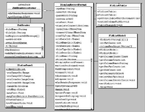
Figure 2: More complex representations of classes, and the relationships between them, are possible in a UML class diagram.
Order Product
Supply Customer
Data Arrange Payment Request Catalog
The salesperson asks for the catalog
Figure 3: A simple use case for an order process represents the behaviors that must be addressed by the system.
Salesperson
<
Request Report
1 * * 1
Figure 4: Actors in a use case are not necessarily people.
File="Department.xml" Namespace="Department":
System User Printer
Department
Figure 5: The XML Metadata Interchange specification brings a standardized way to communicate a class structure to other applications.
Member Of Instructors Postdoc Lecturer Professor Teaching Asst.
Instructor


 More than ever, there is a demand for IT to deliver innovation. Your IBM i has been an essential part of your business operations for years. However, your organization may struggle to maintain the current system and implement new projects. The thousands of customers we've worked with and surveyed state that expectations regarding the digital footprint and vision of the company are not aligned with the current IT environment.
 TRY the one package that solves all your document design and printing challenges on all your platforms. Produce bar code labels, electronic forms, ad hoc reports, and RFID tags – without programming! MarkMagic is the only document design and print solution that combines report writing, WYSIWYG label and forms design, and conditional printing in one integrated product. Make sure your data survives when catastrophe hits. Request your trial now! Request Now.
 Forms of ransomware has been around for over 30 years, and with more and more organizations suffering attacks each year, it continues to endure. What has made ransomware such a durable threat and what is the best way to combat it? In order to prevent ransomware, organizations must first understand how it works.
 Disaster protection is vital to every business. Yet, it often consists of patched together procedures that are prone to error. From automatic backups to data encryption to media management, Robot automates the routine (yet often complex) tasks of iSeries backup and recovery, saving you time and money and making the process safer and more reliable. Automate your backups with the Robot Backup and Recovery Solution. Key features include:
 Business users want new applications now. Market and regulatory pressures require faster application updates and delivery into production. Your IBM i developers may be approaching retirement, and you see no sure way to fill their positions with experienced developers. In addition, you may be caught between maintaining your existing applications and the uncertainty of moving to something new.
 IT managers hoping to find new IBM i talent are discovering that the pool of experienced RPG programmers and operators or administrators with intimate knowledge of the operating system and the applications that run on it is small. This begs the question: How will you manage the platform that supports such a big part of your business? This guide offers strategies and software suggestions to help you plan IT staffing and resources and smooth the transition after your AS/400 talent retires. Read on to learn:
LATEST COMMENTS
MC Press Online