


Some of you may be old methodologists who embraced computer-aided systems engineering (CASE) in the 1980s, like I did. Some of you younger folks may have studied CASE in college. And some of you are just wondering if there are any tools out there to help with the process of designing modern object-oriented systems.
Today, instead of CASE, there is the Unified Modeling Language (UML) and a number of UML-based graphical tools. Many vendors offer UML-based tools that range from free public domain (or open-source) tools to expensive, fully integrated, concept-to-code tools. An organization called Objects By Design hosts a good list on its Web site. My personal favorite--and the tool used to produce the illustrations in this article--is a little product called MetaMill, which is available at $85 for a single-user license and offers excellent multi-user discounts.
Two other companies are at the very high end of the spectrum. These are Rational Software (just acquired by IBM) and TogetherSoft. These products incorporate complete analysis, design, and code-generation tools based on their own proprietary methodologies. The products from both companies average about $3,000 per developer desktop. This may seem expensive, but the CASE tools of the 1980s sometimes cost as much as $20,000 for a single-user workstation license.
UML appeared on the scene back in 1992 with work done by Ivar Jacobson. Meanwhile, additional work was being done by Grady Booch (founder of Rational Software) and James Rumbaugh, who combined forces in 1995 to strengthen Rational Software and combine their individual contributions in object systems modeling into the Rational Unified Process, or RUP.
UML became an open standard for object systems modeling and was given to the Object Management Group (OMG), a member-funded, nonprofit foundation dedicated to object-oriented systems and technologies. The official source of information on UML is www.uml.org (operated by the OMG).
What Is UML?
OK, enough history! What is UML, and why should you care about it? UML is first and foremost a modeling language. It is a method of collecting, storing, and organizing information about a system and its components in a standardized set of files using standards-based language and syntax. The language is robust and was designed from its inception to support graphic representations of objects, their relationships, and their interactions within a system.
00.png)
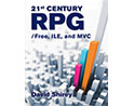
Figure 1: A UML language fragment (Click images to enlarge.)
Figure 1 illustrates a fragment of the UML language text to represent three classes in a class diagram. Needless to say, the language is not for human consumption; rather, it provides a consistent basis for software products to capture and represent UML-based design objects in a standard manner. In theory, you could use the $85 MetaMill product and transfer your designs and diagrams to Rational or TogetherSoft's products or any other UML-based product, and the exchange should be transparent (assuming the vendors followed the UML standard).
The UML includes several standard diagrams and variations of these diagrams. The advantage of the language is that you can switch between diagrams, leveraging the information that you have already captured from the common model language files you create. The UML gives you a means of looking at the data in different views (diagrams) for different purposes (you may use a class diagram to study objects and their relationships while viewing and adding attributes to a sequence diagram to look at application flow).
Due to space limitations, this article simply introduces the diagrams and explains their intended use. See the suggested reading list at the end of the article for books that explain the UML and suggested modeling approaches in detail.
UML Diagrams--Enter at Your Own Risk
A word of caution as I introduce the UML diagrams: Some tools vendors sell tools and formal methodologies, training, and mentoring. Some of these vendors generate more revenue by teaching their methodologies than they do on the sale of tools. While UML tools and diagrams can be tremendously helpful in designing and building an object-oriented system, there is very little science in the process. You are often modeling abstract concepts (remember, computer objects are an abstract representation of reality and are not themselves reality). The flaw in UML is the fact that there is no way of determining if you are modeling the correct objects or if your diagrams make any business sense whatsoever! The risk associated with the use of UML and its related methodologies is that of "analysis paralysis." It is very easy to let modeling become your focus and product, thereby delaying the actual building and implementation of computer systems indefinitely!
That said, let's look at the diagrams and their uses.
The Class Diagram
Perhaps the first step in object-oriented design is to identify your objects. Most methodologists will agree that this step is accomplished by reviewing business requirements and looking for nouns. A noun (a person, place, or thing) is a candidate object. The next step is to look for relationships that exist between these objects. This is facilitated with the UML class diagram.
01.png)
Figure 2: Basic class diagram
Figure 2 shows a preliminary class diagram with three objects. The arrow with a diamond represents a relationship called "composition." In this example, it means that a Catalog is composed of Products and Categories. The simple arrow is called an "association." It means that Products are associated with a Category.
Figure 3 illustrates a slightly more robust class diagram, expanded to include attributes and methods.
02.png)
Figure 3: Class diagram with attributes and methods
In this example, I have added attributes to the Category and Product objects and methods to Catalog and Product. The plus sign means "public." A minus sign would mean "private." You can see that you may represent types, parameters, and return options. This is a microcosm of the full capabilities of the class diagram. There is complete syntax for all types of relationships, including abstract classes, inheritance, and the cardinality of a relationship (e.g., one-to-one, one-to-many, many-to-many, etc.).
Be careful what you use the diagram for. You can rapidly move to a level that represents program code. In fact, many of the tools allow you to generate code from the diagram. Remember that the purpose of the diagram is to allow you to explore the relationships between objects. The class diagrams refer to abstract classes of objects, not specific instances of objects. The object diagram (a variant of the class diagram) allows you to implement specific object instances (e.g., order number 123) to explore detailed relationships and test your class diagrams.
One last word on class diagrams: They are the most scientific of the diagrams implemented in the UML. They are based on the 1980s Entity Relationship Diagrams (ERDs) used in relational data modeling and extended to incorporate methods or behaviors.
Package Diagram
The package diagram, as shown in Figure 4, is a useful method of simplifying your class diagrams.
03.png)
A package represents a collection of classes. In a large system, it may be desirable to do your first cut at modeling using package diagrams and then expand each package to reflect its content. This is a major strength of the software sold by Togethersoft. It is much weaker in other implementations. Use extreme care about what you represent in a package diagram. Programmers also use the package concept. "Package" in modeling may mean package as a Java programmer would expect to use the term, or it may be a conceptual view of objects. Confusion may occur.
Use Case Diagram
I would be remiss if I did not present the use case diagram in this article. I prefer to call it the "useless case diagram" because I find it to be the weakest diagram in the UML. This UML diagram appears to have been designed as a method of communicating business requirements to programmers in a structured form they can understand (don't OO programmers speak normal English?).
04.png)
As shown in Figure 5, the use case diagram consists of actors and use cases. An actor can be a person or a system function outside the scope of the diagram. The actor is depicted as a stick figure of a person. The use case itself is represented by an oval with a name in it. The rectangle in the diagram is the focus area of the system you are working on. At the right side of the diagram is another actor. This actor represents an order fulfillment system. It could be a manual process or an automated system, but it's outside the scope of the current project, which focuses on the ordering process.
As you can see, the use case diagram doesn't tell you much or serve much of a purpose other than to scope a component of your system development effort. Some methodologies expand on the use case diagram with a text-based (not supported via UML), template-oriented approach that supplies a programmer with specific requirements in a text form that is structured to enable the programmer to write code from the text document (see Use Case Driven Object Modeling with UML: A Practical Approach by Doug Rosenberg with Kendall Scott, Addison Wesley, 1999).
Sequence Diagram
The sequence diagram is designed to explore the interaction between objects. Figure 6 shows an example.
05.png)
In the sequence diagram, objects are depicted in the rectangles at the top of the page. The dotted line coming down from the object is called a "lifeline" and is intended to provide an indication of the life of an object within the context of the diagram. The message sent between objects is indicated via a solid line arrow. Notes (the pink rectangle with text and the folded corner) are designed to clarify or explain what is sometimes not obvious in the diagram. A note may be attached to any UML diagram. I have chosen to illustrate this here as there is ambiguity in the UML regarding iterations and what is going on under Product in the diagram.
Collaboration Diagram
The collaboration diagram, like the sequence diagram, is considered in the UML to be an "interaction diagram" that provides different views to explore the interaction between objects. See the example in Figure 7.
06.png)
Figure 7: Collaboration diagram
This diagram uses the same objects defined to the sequence diagram, but it focuses on the object roles instead of the messages sent.
Statechart Diagram
The statechart diagram typifies the origins of UML. UML and its methodologies evolved from a technical, object-oriented design of the 1980s in which OO was used to develop software that controlled machines. Throughout the literature, you will see examples illustrating the control of robots, heating and air conditioning, telephone switches, and the like. State is an inherent part of OO design, and the statechart is a useful diagram to analyze the transitions of state.
07.png)
Figure 8 illustrates a state chart diagram depicting what happens to an ATM machine when a user inserts his ATM card and is prompted for his PIN. The focus here is the transitions in the state of the machine while interacting with the user.
Activity Diagram
The activity diagram is fundamentally a flowchart. It is one of the most useful diagrams in the UML.
08.png)
The diagram in Figure 9 depicts a withdrawal of cash from an ATM machine. The only difference between this diagram and a standard flow chart is the use of "swim lanes" (vertical lines) that separate the interactions between separate people, systems, or objects. The first column in this diagram represents the customer's actions, the second column represents processes performed by the machine, and the third column represents processes performed by the bank's computer.
Component and Deployment Diagrams
These diagrams are used to describe the physical implementation of a system. They may represent components implemented on separate computers (nodes) or separate, self-contained parts of the same system.
09.png)
Figure 10: Collaboration diagram
This diagram depicts the relationship between the processing that occurs on the local ATM machine and that which occurs on the bank's server.
Applied UML
Because of space limitations, this article can only illustrate a microcosm of the capabilities of UML and its diagrams. If you are looking for a design methodology and hands-on experience with UML, the following list of resources may be helpful.
Frankly, I have mixed feelings about the usefulness of UML. It evolved to solve the complex problems of designing software that runs machines. Most of the literature focuses on this problem space. Very little useful documentation exists to apply UML to the modeling of business systems and business applications. However, this does not mean that UML is not an appropriate tool for business system modeling.
I find that the class diagrams are immensely helpful. The sequence diagram and statechart diagrams are rather unclear for the representation of business processes or tasks. The activity diagram is an excellent tool. Pick and choose, read and learn, and make your own informed decisions. Beware of the UML consultants. Frequently, their goal is to sell you services that focus on the design process, which can result in simple projects turning into lengthy projects in which models and diagrams become the most important product of the process.
Resources
The Unified Modeling Language User Guide by Grady Booch, James Rumbaugh, Ivar Jacobson; Addison-Wesley; 1998; ISBN 0201571684
The Unified Modeling Language Reference Manual by James Rumbaugh, Ivar Jacobson, and Grady Booch; Addison-Wesley; 1999; ISBN 020130998X
Applying UML and Patterns by Craig Larman; Prentice Hall; 2002; ISBN 0130925691
Use Case Driven Object Modeling with UML: A Practical Approach by Doug Rosenberg with Kendall Scott; Addison-Wesley; 1999; ISBN 0201432897
TogetherSoft's excellent Web-based UML tutorial
If you are like me and you have spent your career building business systems, you may have to put a clothespin on your nose to read some of these books. There is a great deal of value in them, but you will be frustrated by the stupid examples and pedantic attitude of the authors.
UML is great. Just keep your eyes open, and use what makes sense. Don't jump in blindly to the methodologies. Remember, the vendors of UML tools are selling services and consulting to help you learn to use this stuff.
Bob Cancilla is the author the popular IBM Press book, IBM eServer iSeries: Built for e-business. He also wrote Getting Down to e-business with AS/400, available from MC Press.

Bob Cancilla is the IBM Rational System i Software evangelist helping to set strategy and adoption of IBM Rational application development and life cycle management software for System i customers. Bob joined IBM after over 30 years as an IT executive in the insurance industry. He was the founder of the System i eBusiness electronic user group www.ignite400.org, is the author of four books, and is an industry leader in the areas of application architecture, methodology, and large-scale integrated systems development.
MC Press books written by Bob Cancilla available now on the MC Press Bookstore.
 |
Getting Down to e-business with AS/400 Explains the major issues, concepts, and technologies necessary to implement an AS/400-based e-business solution—from planning for e-business to selecting an ISP. List Price $89.00
Now On Sale
 |
|


 More than ever, there is a demand for IT to deliver innovation. Your IBM i has been an essential part of your business operations for years. However, your organization may struggle to maintain the current system and implement new projects. The thousands of customers we've worked with and surveyed state that expectations regarding the digital footprint and vision of the company are not aligned with the current IT environment.
 TRY the one package that solves all your document design and printing challenges on all your platforms. Produce bar code labels, electronic forms, ad hoc reports, and RFID tags – without programming! MarkMagic is the only document design and print solution that combines report writing, WYSIWYG label and forms design, and conditional printing in one integrated product. Make sure your data survives when catastrophe hits. Request your trial now! Request Now.
 Forms of ransomware has been around for over 30 years, and with more and more organizations suffering attacks each year, it continues to endure. What has made ransomware such a durable threat and what is the best way to combat it? In order to prevent ransomware, organizations must first understand how it works.
 Disaster protection is vital to every business. Yet, it often consists of patched together procedures that are prone to error. From automatic backups to data encryption to media management, Robot automates the routine (yet often complex) tasks of iSeries backup and recovery, saving you time and money and making the process safer and more reliable. Automate your backups with the Robot Backup and Recovery Solution. Key features include:
 Business users want new applications now. Market and regulatory pressures require faster application updates and delivery into production. Your IBM i developers may be approaching retirement, and you see no sure way to fill their positions with experienced developers. In addition, you may be caught between maintaining your existing applications and the uncertainty of moving to something new.
 IT managers hoping to find new IBM i talent are discovering that the pool of experienced RPG programmers and operators or administrators with intimate knowledge of the operating system and the applications that run on it is small. This begs the question: How will you manage the platform that supports such a big part of your business? This guide offers strategies and software suggestions to help you plan IT staffing and resources and smooth the transition after your AS/400 talent retires. Read on to learn:
LATEST COMMENTS
MC Press Online